Schematic Editor — Overview
The Schematic Editor is where you design your circuit: place components, draw wires, assign net labels, and prepare for PCB layout.
What You Can Do Here
| Task | Tool |
|---|---|
| Place components from libraries | Library panel → Double-click |
| Draw wires connecting pins | Wire tool (W) |
| Assign net labels (SDA, SCL, +3V3…) | Label tool (L) |
| Place power symbols (GND, VCC) | GND / VCC toolbar buttons |
| Draw annotations (boxes, text, lines) | Line, Rect, Text tools |
| Edit component properties | Properties panel |
| View net connectivity | Built automatically as you draw |
Workspace
The schematic workspace consists of:
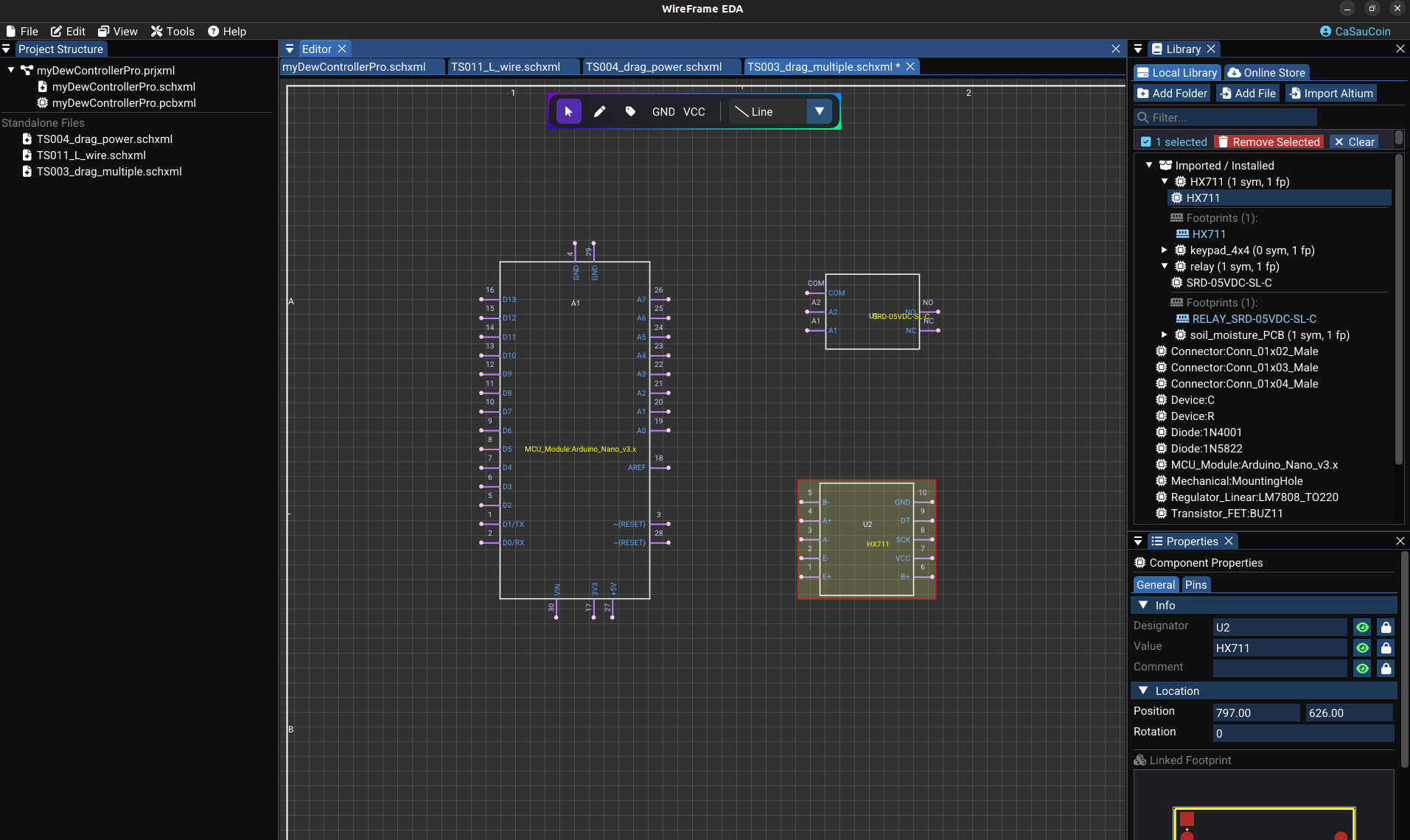
- Canvas — dot grid with an A4 page outline (configurable to A3, custom). Place all components and wires here.
- Toolbar — floating tool buttons above the canvas
- Library panel — symbol list for placing components
- Properties panel — edit properties of the selected item or page settings
- ERC panel — electrical rules check results (details)
- Simulation panel — configure and run SPICE simulations (details)
Toolbar Modes
Each toolbar button activates a drawing mode that determines how mouse clicks are interpreted:
| Mode | Button | Behavior |
|---|---|---|
Select |
▷ Arrow | Click to select, drag to move, drag box to multi-select |
Wire |
─ Wire | Click to start / add corners / end a wire |
Label |
🏷 Label | Click to place a net label |
Text |
T Text | Click to place a text annotation |
Line |
╱ Line | Click start → drag → release |
Rectangle |
□ Rect | Click one corner → drag to opposite |
Circle |
○ Circle | Click center → drag to set radius |
Arc |
⌒ Arc | Click to define arc points |
Polygon |
⬠ Polygon | Click vertices → right-click to close |
Junction |
• Dot | Click to place junction dots manually |
GND |
⏚ GND | Click to place a GND power symbol |
VCC |
↑ VCC | Click to place a VCC power symbol |
The active tool is highlighted cyan. Press Esc to return to Select mode at any time.
Basic Interactions
Selecting objects
| Action | Input |
|---|---|
| Select a single component | Left-click on it |
| Select multiple objects | Drag a selection box on empty canvas |
| Open context menu | Right-click any object |
| Cancel current operation | Esc or right-click |
| Delete selected | Del or Backspace |
| Undo / Redo | Ctrl+Z / Ctrl+Y |
Smart interactions
- Dragging a component — connected wires follow automatically, no broken connections
- Rotating (R) — component rotates 90°, wires adjust to the new pin positions
- Deleting a component — connected wires are also removed (fully undoable)
Section Pages
Continue to the detailed guides for each aspect of schematic design:
| Page | What you'll learn |
|---|---|
| Placing Components | Load libraries, place symbols, edit designators |
| Wiring & Nets | Draw wires, connect pins, net labels, GND/VCC |
| Properties & Attributes | Edit page settings, component attributes, text |
| Graphics & Annotations | Draw boxes, lines, annotations |
| ERC (Electrical Rules Check) | Validate connectivity before PCB conversion |
| Templates & Title Block | Page setup, title block customization |
Related Sections
| Section | What you'll learn |
|---|---|
| Simulation | Run SPICE simulation on your schematic |
| Symbol Library Editor | Create or correct custom schematic symbols |
| AI Copilot | Generate schematics from text descriptions |