Zones and Copper Planes
Copper zones (fills / pours) cover a board area with copper — typically used for ground planes or power planes. This is a standard practice in professional PCB design.
Why Use Zones?
- Ground plane — reduces EMI noise and improves RF signal integrity
- Power plane — reduces voltage drop on power rails
- Larger copper area → lower impedance → better heat dissipation
What Is a Zone?
A filled zone follows its outline while maintaining clearance around objects on other nets. Pads on the zone net connect according to the configured zone connection style.
Each zone has:
| Property | Description |
|---|---|
| Net | The net name (e.g. GND, VCC) |
| Layer | Copper layer (e.g. F.Cu, B.Cu) |
| Priority | Higher-priority zones override lower ones where they overlap |
| Clearance | Minimum gap from pads and traces on other nets |
| Outline | The polygon you draw to define the zone boundary |
Quick Ground Plane
The fastest way — use Fill GND Plane:
- Use Fill GND Plane from the active PCB's zone or toolbar controls.
- WireFrame automatically:
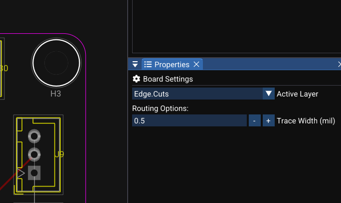
- Reads the board outline from Edge.Cuts
- Creates a GND zone covering the entire board interior
- Computes clearance gaps around all pads and traces not on GND
- Connects GND pads directly into the fill
Creating a Zone Manually
- Select a copper layer (e.g. F.Cu) in the Layer panel
- Use the Draw Polygon tool to draw a closed polygon boundary
- Assign zone properties:
- Net name (e.g.
GND) - Clearance (e.g. 0.2 mm)
- Priority (default: 0)
- Net name (e.g.
- WireFrame computes and renders the copper fill
Zone Priority
When two zones overlap, the zone with the higher priority wins:
The higher-priority zone owns the overlapping copper area; the lower-priority zone remains in the rest of its valid outline.
Image — Overlapping zones with different priorities
Image needed
Capture a GND zone at priority 0 and a smaller VCC island at priority 1. Show the zone outlines, net labels, and resulting filled overlap.
Priority guidelines
- Ground plane → priority 0 (lowest)
- VCC island inside the GND plane → priority 1
- Zone nested inside VCC → priority 2, and so on
How Zones Interact with Nets
| Situation | Result |
|---|---|
| Pad on the same net as the zone | Pad connects directly to the fill (no ratsnest) |
| Trace on the same net passing through | Trace connects to the zone |
| Pad on a different net inside the zone | Clearance gap is maintained around the pad |
| Trace on a different net inside the zone | Clearance gap is maintained around the trace |
Editing Zones
| Property | Editable |
|---|---|
| Net name | ✅ — in Properties panel |
| Layer | ✅ |
| Priority | ✅ |
| Clearance | ✅ |
| Outline (vertices) | ✅ — drag vertices to reshape the boundary |
| Cutouts | ✅ — add excluded shapes inside the zone |
See Also
- Routing — traces interact with zone clearances
- DFM & DRC — zone connectivity is validated during DRC
- Layers & Views — zone visibility follows layer settings