Fabrication and Export
Once your design is complete and DFM passes cleanly, export manufacturing files to send to your PCB manufacturer — or to document your design.
Export Types Overview
| File type | Format | Purpose |
|---|---|---|
| Gerber | RS-274X .gbr |
PCB fabrication — copper, mask, silk, outline layers |
| Drill | Excellon .drl |
Via and hole positions for CNC drilling |
| BOM | CSV .csv |
Bill of Materials for component ordering |
| Schematic PDF | PDF .pdf |
Printable schematic documentation |
| Toner Transfer PDF | PDF .pdf |
Hobbyist — per-layer PDFs for manual PCB making |
Schematic PDF Export
Exports your schematic as a vector PDF for printing or sharing.
Steps:
- Open the Schematic tab you want to export
- Select File → Export → Export Schematic to PDF
- Choose a filename and directory
- Click Export
PDF content:
| Element | Rendering |
|---|---|
| Components | Symbol outlines, pins, designator and value text |
| Wires and junctions | Black/grey lines and dots |
| Graphics | Rectangles, circles, text annotations |
| Title block | Page border, title, company, revision, date |
Colors are converted to black and grey for print-friendly output.
PCB Gerber Export
Gerber is the industry-standard format sent to PCB manufacturers. Each layer produces a separate .gbr file.
Steps:
- Open the PCB tab
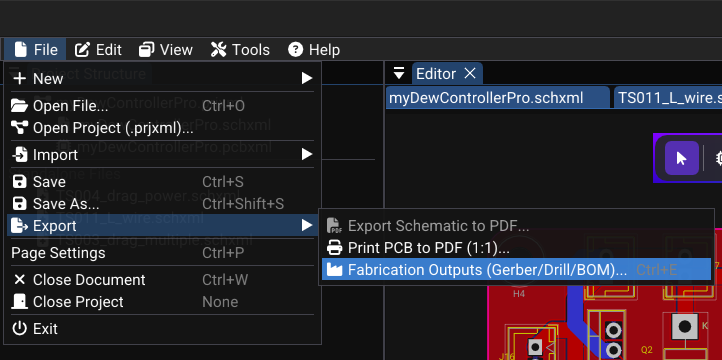
- Select File → Export → Fabrication Outputs (Gerber/Drill/BOM) or Tools → Fabrication Output
- Select the layers to export:
| Layer | Example filename | Purpose |
|---|---|---|
| F.Cu | MyBoard-F_Cu.gbr |
Front copper |
| B.Cu | MyBoard-B_Cu.gbr |
Back copper |
| F.SilkS | MyBoard-F_SilkS.gbr |
Front silkscreen |
| F.Mask | MyBoard-F_Mask.gbr |
Front solder mask openings |
| B.Mask | MyBoard-B_Mask.gbr |
Back solder mask openings |
| Edge.Cuts | MyBoard-Edge_Cuts.gbr |
Board outline for cutting |
- Choose the output directory
- Click Export — one
.gbrfile is generated per selected layer - (Optional) Compress all files into a ZIP to send to the manufacturer
Which files to send?
Typically: F_Cu, B_Cu, F_SilkS, F_Mask, B_Mask, Edge_Cuts, and the drill .drl file. Always check your manufacturer's specific requirements.
Drill File Export
The drill file contains all hole locations and diameters — vias and mechanical holes.
Format: Excellon NC drill (text-based coordinate format)
Data included: - X, Y coordinates for each via and hole - Drill diameter per tool - Plated vs. non-plated hole separation
BOM Export (Bill of Materials)
The BOM is a parts list used to order components for assembly.
Steps:
- Open the fabrication output workflow.
- Include the BOM CSV in the coordinated package.
- Open in Excel, LibreOffice Calc, or Google Sheets
BOM file columns:
| Designator | Value | Footprint | Layer |
|---|---|---|---|
| R1 | 10kΩ | R_0603_1608Metric | Top |
| R2 | 330Ω | R_0603_1608Metric | Top |
| C1 | 100nF | C_0805_2012Metric | Top |
| U1 | STM32F103 | LQFP-48 | Top |
Before exporting the BOM
Only footprints with a non-empty Value field are included. Verify that all components have values assigned.
Toner Transfer PDF (Hobbyist)
Toner Transfer PDF is a WireFrame feature designed for makers and hobbyists who produce PCBs manually using toner transfer or UV film methods.
- Generates each selected layer as a separate PDF page
- Output is true 1:1 scale — no page scaling
- Automatically mirrors layers that need to be printed reversed (e.g. F.Cu)
- WYSIWYG silkscreen — text renders exactly as it appears on the physical board
Steps:
- Open the Fabrication dialog
- Select Toner Transfer PDF as the export type
- Choose the layers to include (e.g. F.Cu, B.Cu)
- Click Export — each layer becomes a separate page in the PDF
- Print on glossy paper at 100% scale (no fit-to-page)
Built-in Gerber Viewer
WireFrame includes a Gerber viewer to inspect exported files without external software.
How to use:
- Select Tools → Gerber Viewer and open a generated
.gbrfile, or use another trusted Gerber viewer. - Select representative copper, mask, silkscreen, and outline outputs.
- Pan and zoom to verify:
- Trace continuity
- Pad alignment and spacing
- Board outline shape
Visually confirm trace continuity, pad flashes, apertures, and the board outline before sending the package to a manufacturer.
Complete Export Workflow
- Run DFM/DRC and resolve every release-blocking error.
- Generate the coordinated fabrication package.
- Review representative Gerber X2 layers and both drill outputs.
- Check IPC-D-356A, BOM, and the package manifest.
- Archive only the verified board revision and send that archive to the manufacturer.
Image — Verified fabrication package
Image needed
Capture the fabrication output dialog beside the generated package contents. Show the board revision and filenames, but no private customer path.
Fabrication package contents
The release workflow can generate a coordinated package rather than a set of unrelated exports:
| Output | Purpose |
|---|---|
| Gerber X2 | Copper, mask, silkscreen, and board geometry with generation metadata |
| PTH / NPTH drill files | Separates plated electrical holes from unplated mechanical holes |
| IPC-D-356A netlist | Electrical connectivity reference for fabrication test and CAM review |
| BOM CSV | Designators, values, footprints, and placement layer |
| Manifest / README | WireFrame version, generation time, and package inventory |
Inspect the archive
A successful export does not prove manufacturability. Confirm that Edge.Cuts is closed, drill classifications are correct, every expected layer is present, and the package matches the board revision being released.
See Also
- DFM & DRC — run checks before exporting
- Layers & Views — layer selection for export
- File Formats — detailed file format specifications